3D Printing Tolerance: What It Is and How to Improve (2024)

Discover the typical tolerances for different 3d printing technologies and materials, plus practical tips to improve them for optimal part performance.
What is 3D Printing Tolerance?
3D printing tolerance refers to the allowable deviation or variation in the final dimensions of a printed object compared to its original design specifications.
It represents how much a part's actual dimensions can differ from the intended design while still being considered acceptable for its function.
How Much Tolerance for 3D Printing?
Understanding how different 3D printing technologies and materials behave in terms of dimensional accuracy is essential for achieving the desired fit and function.
Typical Tolerances of Different 3D Printing Technologies
While specific tolerance values vary depending on the 3D printing technology used, here are typical tolerances often seen in different processes:
Technology | Typical Tolerances(mm) | Description |
|---|---|---|
|
| FDM extrudes thermoplastic filaments layer by layer. Factors like layer height, material flow, and cooling affect accuracy. |
|
| SLA uses a UV laser to cure liquid resin layer by layer, producing high-precision parts with fine details. |
|
| SLS uses a laser to sinter powdered materials layer by layer, with slightly lower accuracy than SLA. |
DMLS/SLM |
| DMLS and SLM use a laser to fuse metal powders, offering precision in producing strong metal parts. |
|
| PolyJet jets photopolymer resin layers and cures them with UV light, achieving high precision and smooth surfaces. |
In summary:
For precise applications, SLA, PolyJet, and metal-based processes like DMLS and SLM offer tighter tolerances.
FDM and SLS are more suitable for general-purpose parts with moderate tolerance requirements.
Tolerance of Different Materials Used in 3D Printing
Material properties, such as shrinkage, flexibility, and heat resistance, can significantly impact the tolerances achievable in 3D printing.
Material | Typical Tolerances(mm) | Description | Tolerance Considerations |
|---|---|---|---|
|
| Commonly used in FDM. Shrinkage during cooling can cause deviations in size. |
|
|
| Used in SLA and PolyJet. Solidify under UV light, providing high accuracy. | Different resins vary in shrinkage; standard resins are more stable. |
Metals |
| Used in DMLS/SLM. Strong and precise but prone to shrinkage during cooling. | Metals need post-processing like machining for precise fits. |
|
| Common in SLS for functional parts, but prone to higher shrinkage rates. | Nylon may require post-processing to improve accuracy. |
|
| Elastic materials with high flexibility, prone to significant deformation. | Flexible materials have looser tolerances due to deformation. |
If you're looking for high-quality 3D prints with precise tolerances tailored to your specific needs, Unionfab is here to help. As Asia’s leading 3D printing company, Unionfab operates over 1,000 industrial-grade 3D printers and specializes in rapid prototyping and on-demand production. Unionfab, ready to bring your projects to life!

Key Factors Affect Tolerance and How to Improve
This section outlines the primary issues impacting tolerance, along with practical solutions for addressing them to achieve better tolerance, across four main categories: Material Properties, Printing Parameter Settings, Equipment, Support Structure, and Post-Processing.
1. Material Property
Thermal Warping: Cooling shrinkage can deform parts, especially large or thin structures.
Solution: Use thermally stable materials or a heated bed.
Shrinkage and Expansion: Cooling can alter part dimensions, affecting tolerance.
Solution: Account for shrinkage in design and adjust model size.
Inconsistent Flow Rate: Viscosity or flow issues may cause uneven material flow, reducing quality.
Solution: Use compatible materials and regularly calibrate the extruder.
2. Printing Parameter Settings
Layer Thickness: Incorrect layer height leads to dimensional errors.
Solution: Set accurate layer height and reduce thickness for precision.
Print Head Positioning Error: Miscalibration causes dimensional and shape deviations.
Solution: Regularly calibrate the print head for accurate positioning.
3. Equipment
Equipment Stability: Vibrations can cause print deviations, especially at high resolution.
Solution: Ensure stable operation and regular maintenance.
Printer Calibration: Inaccurate calibration affects dimensional precision.
Solution: Regularly calibrate the print head, platform, and nozzle.
Maintenance: Worn or clogged parts disrupt accuracy.
Solution: Clean the nozzle, lubricate moving parts, and maintain the cooling system.
4. Support Structure and Post-Processing
Surface Residue: Removing supports can leave marks that affect tolerance.
Solution: Use removable materials and increase the support gap in the design.
Surface Roughness: Support contact areas may become rough, affecting appearance and accuracy.
Solution: Use high-resolution settings or reduce contact areas; polish post-print.
Post-Processing: Sanding or polishing can change part dimensions.
Solution: Consider post-processing effects in design and avoid overhandling.
How to Choose the Best Type of Fit in 3D Printing
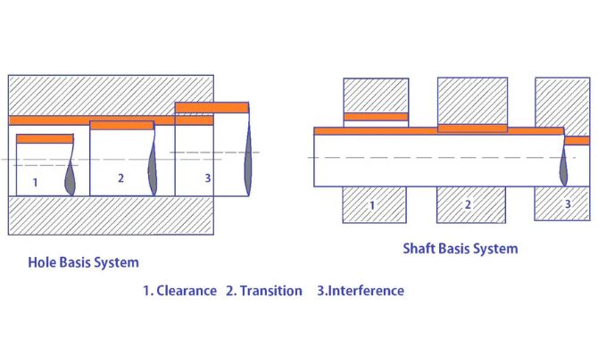
Choosing the best type of fit in 3D printing depends on the specific application requirements, such as part functionality, assembly method, and material properties. Here's a quick guide on when to use each type of fit in 3D printing.

Source: kdmfab.com
1. Clearance Fit
When to Use: If parts need to move freely against each other or be easily assembled and disassembled (e.g., gears, sliding mechanisms).
Characteristics: There is always a gap between the two parts, allowing for movement or easy insertion.
Best for:
Components requiring loose tolerances.
Applications where ease of assembly and movement is important.
3D printed parts that may have slight dimensional inaccuracies.
Example: Shafts and holes where the shaft can slide or rotate easily.
2. Transition Fit
When to Use: If parts need to fit together with a slight push or require light press-fitting for stability.
Characteristics: There may be either a small gap or slight interference, depending on the tolerance.
Best for:
Situations where a part must stay in place but still be removable without too much force.
Applications where the fit needs to balance between easy assembly and firm placement.
3D printed parts with moderate tolerance control.
Example: Bearings that need to be firmly seated but removable without damage.
3. Interference Fit
When to Use: If parts need to be tightly secured and not move relative to each other after assembly (e.g., press-fitted components).
Characteristics: The parts must be forced together, creating a very tight and permanent bond.
Best for:
Applications requiring maximum stability and no movement between parts.
High-tolerance parts where exact precision is needed.
3D printed parts where materials allow for flexibility or post-processing for precise fit.
Example: Permanent press fits for gears, pins, or wheels that shouldn't rotate after assembly.
⠀In summary:
Clearance Fit: Suitable for parts needing free movement or easy assembly.
Transition Fit: Ideal for parts that need a firm, but not overly tight, connection.
Interference Fit: Best for parts requiring a secure, immovable fit.
How to Test the 3D Printing Tolerance?
1. Design a Tolerance Test Model
Create or download a model with features like hole sizes, overhangs, thin walls, and gaps. Popular options include:
Calibration cubes: Measure dimensional accuracy.
Tolerance gauge models: Test fit with varying hole sizes.
Benchmark parts: Evaluate flatness, parallelism, and overhangs.
2. Print the Test Model
Use standard printer settings (layer height, speed, material). Print without supports if possible to ensure precision.
3. Measure Critical Dimensions
Use precision measurement tools such as calipers or micrometers to measure external dimensions, hole diameters, and gaps. Compare to design values to check if the tolerance is within limits.
4. Test Fits
For parts that need to fit together, try assembling them. Check if parts with clearance or interference fits perform as expected:
Clearance fit parts should easily slide into place.
Interference fit parts should require some force for assembly but stay firmly in place.
Use feeler gauges to measure gaps between fitting parts to ensure the tolerance is within an acceptable range.
5. Assess Dimensional Deviation
Compare measured values to the design and calculate deviations to determine if the part is within acceptable tolerance (e.g., ± 0.2mm).
6. Evaluate Warping and Shrinkage
Check for warping or shrinkage, especially in large or flat parts, as they indicate calibration issues.
7. Check Surface Quality and Layer Consistency
Examine surface finish and layer consistency, as poor adhesion or roughness can affect fitting and tolerance.
8. Repeat with Different Settings
Test with varying layer heights, speeds, and materials to optimize for better accuracy and tolerance. Compare results to refine printer settings.
Conclusion
In 2024, 3D printing tolerance remains a critical factor in ensuring that printed parts meet design specifications and function properly. By understanding typical tolerances across different technologies and materials, users can make informed decisions based on the accuracy required for their projects.
Addressing key factors such as material properties, printer settings, equipment maintenance, and post-processing is essential for improving dimensional precision. Additionally, choosing the appropriate fit—whether clearance, transition, or interference—ensures optimal part performance.
FAQs
What is fit tolerance?
Fitness tolerance in the context of engineering refers to how well parts fit together with respect to their allowable dimensional deviations. It defines the acceptable range of dimensional variation between two mating parts (e.g., a shaft and a hole). This ensures parts fit and function properly, with categories like clearance fit, transition fit, and interference fit dictating how tightly or loosely the parts assemble.
How much tolerance for 3D printing PLA?
For PLA, the typical tolerance ranges from ±0.1 mm to ±0.2 mm. The exact tolerance depends on factors like printer calibration, layer height, and the design of the part. PLA usually provides good dimensional stability, but slight deviations can still occur due to cooling and layer alignment.
What is the 5 mm rule in 3D printing?
The 5 mm rule in 3D printing refers to a general guideline suggesting that any unsupported horizontal overhangs should not exceed 5 mm to avoid sagging or deformation during printing. For overhangs larger than 5 mm, support structures are usually required to maintain print quality.
What are good tolerances for 3D printing?
Good tolerances for 3D printing depend on the technology, materials used, and the specific application requirements. Here are general guidelines for different 3D printing technologies:
Technology | Typical Tolerance | Suitable for |
|---|---|---|
FDM | ±0.1 mm to ±0.5 mm | Prototypes, non-functional parts, and larger structures where precision is not the highest priority. |
SLA | ±0.05 mm to ±0.15 mm | High-detail parts, medical models, and small components with fine features. |
SLS | ±0.1 mm to ±0.3 mm | Functional prototypes, durable parts, and complex geometries. |
DMLS/SLM | ±0.05 mm to ±0.2 mm | Metal parts that require high strength and precision, such as aerospace components and medical implants. |
PolyJet | ±0.05 mm to ±0.1 mm | High-resolution models with smooth surfaces, dental models, and detailed visual prototypes. |
General Guidelines:
For high-precision applications, aim for a tolerance of ±0.05 mm to ±0.1 mm.
For general-purpose prototypes or larger, non-critical parts, tolerances of ±0.2 mm to ±0.5 mm are acceptable.

