
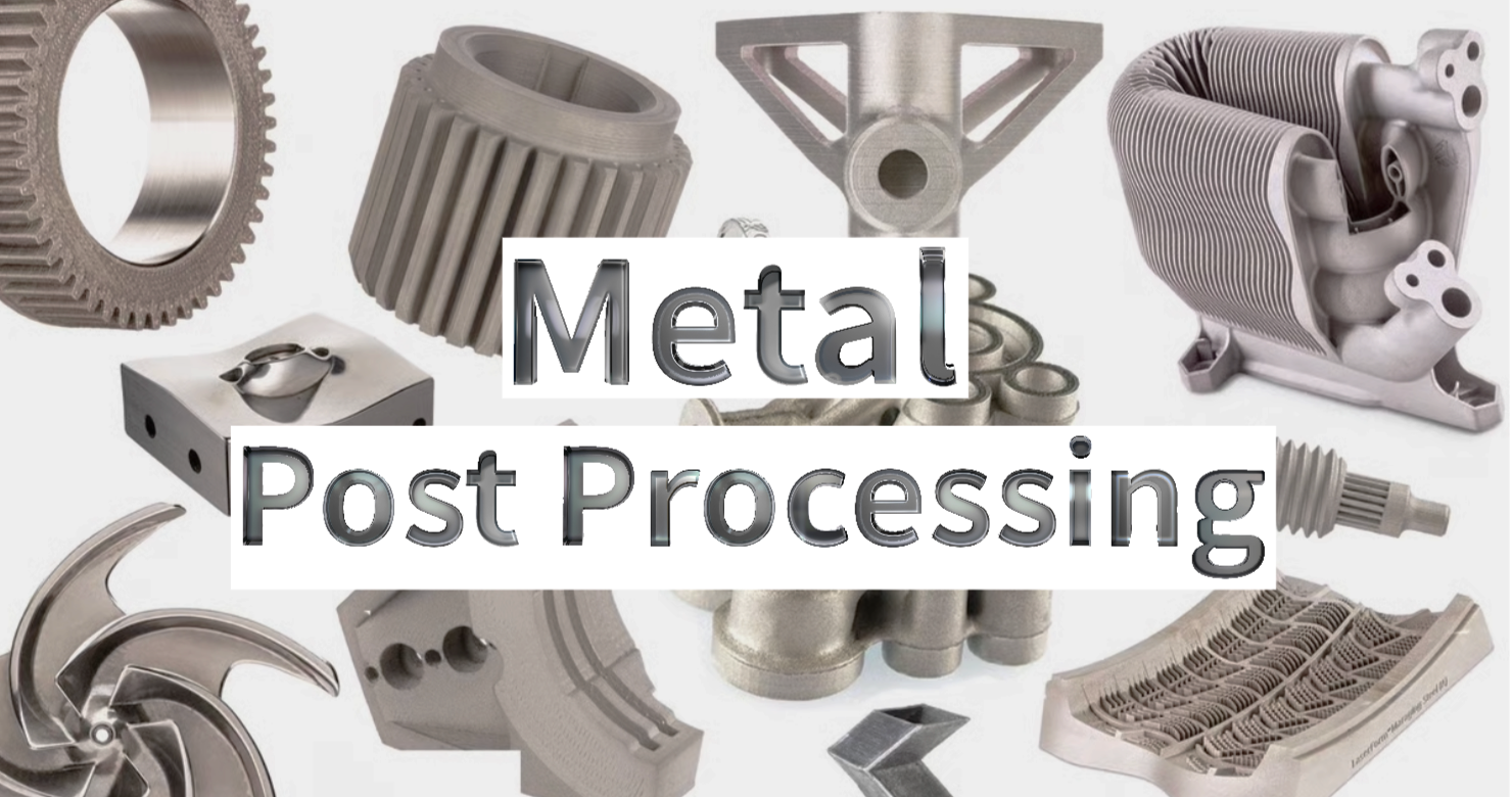
Learn metal 3D printing post-processing methods, from heat treatment and CNC machining to surface finishing, and how to choose the right method for your parts.
Introduction
A metal 3D printed aerospace bracket may come out of the printer with its final geometry, but it is not necessarily ready for installation. The part still need to be separated from the build plate, relieved of residual stresses, machined at critical interfaces, or finished to meet the required surface condition.
This is why metal 3D printing often involves more than the printing process itself. Depending on the manufacturing process and final application, a printed part may require one or more post-processing operations before it can be used as a finished component.
In this guide, we will explain what metal 3D printing post-processing is, the common techniques used, how post-processing differs across major metal AM processes, and how to choose the right post-processing techniques for your parts.
What Is Metal 3D Printing Post-Processing?
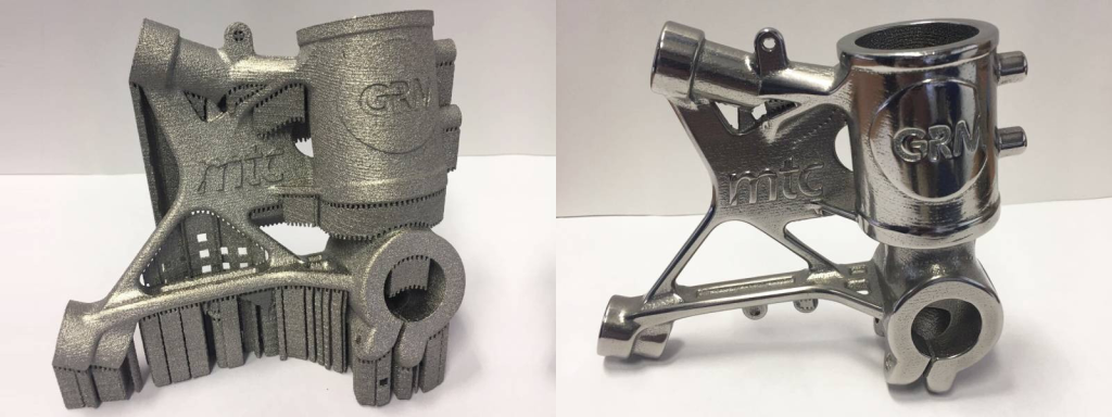
Post-processing in the context of metal 3D printing refers to the additional steps and treatments applied to a part after it has been produced through an additive manufacturing (AM) process.
Different metal additive manufacturing processes—including Powder Bed Fusion (PBF), Directed Energy Deposition (DED), Metal Binder Jetting (MBJ), and Metal Extrusion (MEX)—produce parts in different initial states and therefore require different post-processing approaches.
At the same time, the final requirements of the part, such as mechanical properties, dimensional accuracy, and surface finish, determine which additional treatments are necessary.
Together, these operations transform an as-printed build into a finished metal component.
Common Post-Processing Techniques for Metal AM
Laser Powder Bed Fusion (LPBF, often referred to as SLM) is one of the most widely used metal 3D printing processes, so it provides a useful example for understanding the common post-processing steps applied to metal AM parts.
A typical LPBF post-processing workflow may involve powder and support removal, heat treatment, machining, and surface finishing. However, not every part requires every operation. The exact combination depends on the requirements of the finished component.
Powder and Support Removal
Metal 3D printing can leave unused powder, support structures, and other unwanted material on or inside the printed part. These materials need to be removed before the part can be further processed or delivered.
Depowdering: Removes loose powder trapped inside internal cavities, channels, lattice structures, and other difficult-to-access areas. It is particularly relevant to powder bed fusion processes.
Support Removal: Removes sacrificial support structures used to build overhangs, anchor components to the build plate, or manage heat during printing.
Stress Relief and Mechanical Properties
The rapid heating and cooling cycles involved in metal 3D printing can create residual stresses and produce process-specific microstructures. Heat treatment can therefore be used to relieve stress, stabilize the part, and achieve the required material properties.
Common heat treatment methods include:
Stress Relief: Typically performed before removing the part from the build plate to reduce residual thermal stresses and minimize the risk of distortion.
Annealing: Heats the part to a controlled temperature followed by controlled cooling to modify the microstructure, relieve stress, and improve ductility.
Hot Isostatic Pressing (HIP): Applies elevated temperature and gas pressure to reduce internal porosity and improve material integrity and fatigue performance.
Solution Treatment: Dissolves specific phases into a solid solution and is commonly used as part of the heat treatment cycle for precipitation-hardening alloys.
Aging (Precipitation Hardening): Promotes the formation of fine precipitates after solution treatment to increase strength and hardness.
Dimensional Accuracy
Metal 3D printing can produce highly complex geometries, but some functional features may still require machining to achieve tight engineering tolerances or precise mating conditions.
Common secondary machining operations include:
CNC Milling: Finishes flat mounting surfaces, mating faces, datum surfaces, and other critical features.
CNC Turning: Finishes cylindrical features, shafts, and rotational components.
Drilling & Reaming: Brings printed holes to precise nominal diameters and required fits.
Tapping & Thread Milling: Produces reliable internal threads where printed threads do not meet functional requirements.
Precision Grinding: Produces highly accurate and smooth surfaces for sealing faces, bearing journals, and tight fits.
Tip: Designers should provide sufficient machining allowance and accessible reference datums on critical surfaces when preparing parts for metal 3D printing.
Surface Finishing
As-printed metal surfaces often retain partially fused particles and visible layer-related texture. Surface finishing can be used to modify the texture, improve cleanability, enhance corrosion or wear resistance, or achieve a specific appearance.
1. Smoothing & Mechanical Finishing
Abrasive Blasting (Sand / Bead Blasting): Uses abrasive media to remove loose particles and create a more uniform matte or satin finish.
Vibratory Finishing / Tumbling: Uses abrasive media and vibration to deburr edges and produce a more consistent surface finish across batches of parts.
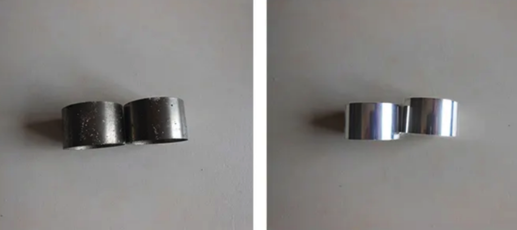
Electropolishing: Uses an electrochemical process to selectively remove microscopic surface peaks, improving surface smoothness, cleanability, and passive corrosion resistance.
Chemical Polishing: Uses controlled chemical dissolution to smooth accessible external and internal surfaces that may be difficult to reach mechanically.
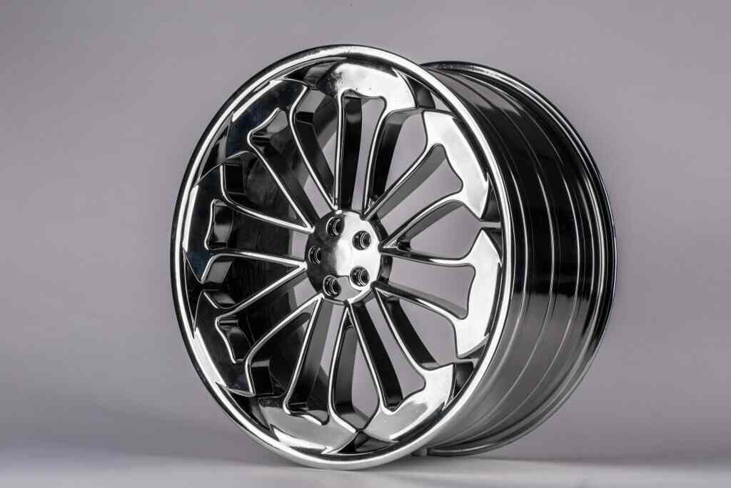
Manual / Buff Polishing: Uses progressively finer abrasive compounds to achieve cosmetic, high-luster, or mirror-like finishes.

2. Corrosion, Wear & Surface Protection
Passivation: Chemically treats stainless-steel surfaces to remove contaminants and promote the formation of a protective passive oxide layer.
Anodizing: Commonly used for aluminum components to create a controlled oxide layer that improves corrosion and wear resistance and can provide a decorative finish.
Plating (Electro- / Electroless): Deposits a metallic coating such as nickel or chrome to modify surface hardness, wear resistance, corrosion resistance, lubricity, or electrical properties.
Wear-Resistant Coatings (PVD / DLC / Thermal Spray): Apply protective coatings to improve wear resistance, friction behavior, corrosion resistance, or service life.
3. Appearance & Traceability
Painting & Powder Coating: Applies a durable organic or polymer coating for color customization, environmental protection, and a uniform appearance.
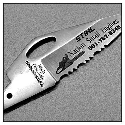
Laser Engraving & Marking: Permanently marks serial numbers, QR/Data Matrix codes, logos, and other identification information for traceability.
Have a metal 3D printing project requiring specific finishes?
Upload your CAD files to Unionfab for free DFM feedback and custom post-processing options.
Post-Processing for Different Metal AM Processes
Different metal AM processes produce parts in fundamentally different states, which dictates their post-processing workflows.
The primary difference lies in the initial as-printed state:
Direct processes (PBF and DED) produce consolidated, near-full-density metal parts directly on a platform or substrate, requiring baseline thermal relief and mechanical separation.
Indirect processes (MBJ and MEX) produce binder-bound "green" parts that require furnace consolidation (debinding and sintering) before they reach their final density and mechanical properties.
To help you distinguish between what is handled automatically and what requires your specification, the typical post-processing requirements for the four main technologies are summarized below:
The table below shows a typical supplier workflow. Exact included steps vary by material, machine, part geometry, and service package.
Process | Typical Baseline Steps | Application-Driven Steps (Available on Request) |
|---|---|---|
Powder Bed Fusion (PBF) | Depowdering; stress-relief heat treatment; platform separation; support removal | Mechanical Properties: Advanced heat treatment, HIP |
Directed Energy Deposition (DED) | Stress relief or normalizing; substrate separation (when applicable) | Mechanical Properties: HIP, shot peening |
Metal Binder Jetting (MBJ) | De-caking and depowdering; debinding and sintering; standard surface cleaning | Mechanical Properties: HIP, alloy-specific heat treatment |
Metal Extrusion (MEX) | Debinding and sintering; support separation (at ceramic release interface); standard bead blasting | Mechanical Properties: Alloy-specific heat treatment |
How to Choose the Right Post-Processing Method
Choosing the right post-processing sequence requires balancing functional requirements, material properties, cost, and lead time. Too much post-processing can increase production costs, while too little can affect part performance and service life.
To determine the right post-processing strategy, consider these four key factors:
1. Functional & Mechanical Requirements
Fatigue & High-Stress Applications: For aerospace, defense, and medical components, HIP can reduce internal porosity, while shot peening improves fatigue resistance and polishing reduces surface defects.
Wear & Thermal Resistance: High-friction tooling and turbine blades may require specialized coatings such as DLC (Diamond-Like Carbon), PVD, or thermal spray coatings.
Corrosion Resistance: Stainless steel parts used in marine or chemical environments may require passivation or electropolishing to restore the protective chromium oxide layer.
2. Dimensional & Assembly Constraints
Mating Interfaces & Bearings: As-printed tolerances for LPBF are typically around ±0.1 to ±0.2 mm. If the assembly requires tight fits (e.g., ISO H7/g6) or flat sealing surfaces, specify secondary CNC milling, turning, or grinding with enough machining allowance.
Fasteners & Ports: Avoid relying on as-printed internal threads for structural fastening. Use secondary tapping, thread milling, or thread inserts where needed.
3. Surface Roughness (Ra) Targets
Non-critical/Internal Structural Parts: As-printed or basic bead-blasted surfaces (Ra 6–10 µm) are often sufficient and provide a cost-effective solution.
Fluid & Airflow Channels: Internal passages in heat exchangers or manifolds may require surface smoothing to reduce pressure loss. Consider chemical polishing, abrasive flow machining (AFM), or electropolishing.
Cosmetic or Cleanroom Applications: Consumer hardware and surgical tools may require centrifugal disc finishing, chemical polishing, or multi-stage manual buffing to achieve smooth (Ra < 0.4 µm) or mirror finishes.
4. Cost and Lead Time Trade-Offs
Post-processing can add cost and lead time to a metal 3D printed component. To control costs:
Keep heat treatment to standard processes (such as batch stress relief) unless higher mechanical requirements call for vacuum aging or HIP.
Machine only critical mating features and datums instead of machining the entire part.
Group parts for batch surface treatments such as tumbling or bead blasting instead of using labor-intensive manual polishing.
Design Tips for Easier Metal AM Post-Processing
Optimizing your CAD model for both additive manufacturing and post-processing—often referred to as Design for Additive Manufacturing and Post-Processing (DfAM/DfP)—can help reduce labor, cost, and material waste.
Design Tip | What to Do | Why It Matters |
|---|---|---|
Add Machining Stock Where Needed | Add 0.8 mm to 1.5 mm of extra material to surfaces, mating faces, and hole diameters that require secondary CNC machining. | Provides enough material to remove surface roughness and correct minor dimensional variations from printing. |
Include Fixturing Features and Datums | Add temporary clamping tabs, flat alignment surfaces, or locating holes where needed. | Makes complex or topology-optimized parts easier to secure during CNC machining and inspection. |
Design for Easy Depowdering | For enclosed cavities and conformal cooling channels, include at least two powder evacuation openings, ideally on opposite sides. Openings of 4–6 mm or more can help powder escape. | Makes it easier to remove loose powder during depowdering and cleaning. |
Minimize and Optimize Support Structures | Orient the part to reduce support requirements. Where supports are necessary, avoid placing them on cosmetic surfaces, sealing areas, or hard-to-reach internal features. | Reduces support removal work and helps protect important surfaces and features. |
Allow Space for Wire EDM Separation | Leave enough accessible space between the lowest functional feature and the build substrate for wire EDM cutting. A clearance of around 3–5 mm can be used where applicable. | Provides enough access for part separation without interfering with functional features. |
Account for Shrinkage in Indirect Processes (MBJ & MEX) | Keep wall thicknesses as uniform as possible and account for approximately 15% to 20% shrinkage during sintering. | Helps reduce uneven shrinkage, warping, and cracking during thermal processing. |
Conclusion
Metal 3D printing is rarely a "one-button" production process. Technologies such as LPBF, DED, and Metal Binder Jetting can produce complex internal geometries, lightweight lattice structures, and consolidated assemblies, but post-processing is often necessary to turn printed parts into finished engineering components.
From powder removal and stress-relief heat treatment to precision CNC machining and electrochemical surface finishing, each post-processing step serves a specific purpose.
By considering mechanical, dimensional, and surface requirements early and designing for post-processing from the start, you can reduce production time, control costs, and achieve the required performance for your application.
Special offer: Get 10% off your first order when you sign up as a new customer.
FAQs
What is post-processing in metal 3D printing?
Post-processing refers to the operations performed after metal 3D printing to remove residual material, relieve stresses, improve mechanical properties, achieve required dimensional tolerances, or enhance surface finish.
What are the common post-processing methods for metal 3D printing?
Common methods include depowdering, support removal, stress-relief heat treatment, Hot Isostatic Pressing (HIP), secondary CNC machining, bead blasting, tumbling, electropolishing, and surface coating.
What post-processing techniques improve the surface finish of metal 3D printed parts?
Abrasive blasting (sand/bead blasting), vibratory tumbling, grinding, mechanical polishing, electropolishing, and chemical polishing can all be used to reduce surface roughness and improve finish.
What post-processing techniques improve the mechanical properties of metal 3D printed parts?
Heat treatment (such as stress relieving, solution annealing, and aging) and Hot Isostatic Pressing (HIP) are primary methods to optimize ductility, strength, and density. Additionally, shot peening is commonly used to induce compressive surface stresses and improve fatigue resistance.
How does post-processing improve dimensional accuracy?
Secondary CNC machining, wire EDM, reaming, tapping, and precision grinding remove excess stock from critical interfaces. These subtractive processes can achieve much tighter tolerances than the as-printed state, although the achievable accuracy depends on the machining operation, machine, material, and inspection method.
What is the difference between depowdering and support removal?
Depowdering removes loose, unfused metal powder trapped inside or around the part, while support removal mechanically or manually detaches solid, printed structures used to anchor the part during printing. They are distinct steps addressing different physical states of the material.
Does post-processing increase metal 3D printing cost and lead time?
Yes. Post-processing often accounts for a significant portion of the total cost and adds to the overall lead time. However, carefully specifying only the secondary operations required for your application's functional, dimensional, and cosmetic needs helps keep costs under control.